

The Authority in Global Agricultural Chemistry & Bio-Resources
Automatic Layer Chicken Cage Maintenance: Checks That Limit Downtime
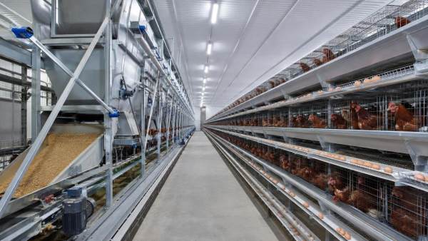
Automatic Layer Chicken Cage Maintenance: Checks That Limit Downtime
A stopped manure belt, a stalled egg conveyor, or a feed line that runs unevenly can disrupt far more than one row of cages. In a commercial layer house, equipment faults can quickly create secondary work: eggs accumulate where they should not, feed access becomes inconsistent, manure removal is delayed, and operators may need to enter areas that are normally served by automated systems. For after-sales maintenance personnel, the practical objective is not simply to repair the failed component. It is to identify the condition that caused the failure, restore safe operation, and prevent the same fault from returning during the next production cycle.
Most extended outages develop from small, observable changes rather than sudden catastrophic failures. A motor may draw more current because a belt is tracking poorly. A conveyor may hesitate because bearings are contaminated with dust and moisture. A feed trolley may stop at one end of the house because a limit switch is misaligned, not because the drive motor has failed. Maintenance routines that focus on these early signals usually produce more reliable results than reactive replacement of parts after a complete stoppage.
Start With the Fault Pattern, Not the Failed Part
When an automated subsystem stops, replacing the most visible failed item can be tempting. A tripped overload may lead to a motor replacement; a broken chain link may lead to a new chain section. Yet the original problem may be excessive drag, incorrect tension, misalignment, obstruction, poor electrical connections, or an unsuitable operating sequence. If that root condition remains, the replacement part can fail just as quickly.
A useful first distinction is whether the problem is isolated, repeating, or progressive:
- Isolated faults often follow a foreign object, a temporary power interruption, an operator setting error, or accidental impact during cleaning.
- Repeating faults tend to point to loose terminals, sensor positioning, belt tracking, intermittent wiring, inadequate tension, or a component that is incorrectly specified for its duty cycle.
- Progressive faults usually show warning signs over time, such as increasing noise, heat, vibration, slower travel, uneven loading, or rising motor overload trips.
Before isolating power, collect basic evidence from the operator: which line stopped first, whether the fault occurred at startup or under load, whether it appears at a certain location, and whether any alarms, overload indications, or abnormal sounds were observed. Recording the time and location matters. A manure belt that trips only during humid morning operation suggests a different investigation from one that trips every time a particular cage tier reaches a transfer point.
Trend records do not need to be complex. A maintenance log that captures component, location, symptom, corrective action, parts used, and recurrence date can reveal recurring weaknesses. It also helps distinguish normal consumable wear from installation, adjustment, or operating problems.
Make Isolation and Access Part of the Maintenance Plan
Layer-cage automation combines moving conveyors, gear drives, electrical panels, elevated work positions, and, in some installations, pneumatic or water systems. Maintenance personnel should not treat a stopped line as harmless merely because it is no longer moving. Stored mechanical energy, automatic restart commands, suspended loads, and energized control circuits can all create hazards during inspection.
For facilities subject to U.S. occupational safety rules, OSHA’s Control of Hazardous Energy standard requires procedures for isolating hazardous energy during servicing and maintenance, including lockout or tagout practices where applicable. The standard also addresses employee training, periodic inspections, and communication when outside personnel are involved. (Source: U.S. Occupational Safety and Health Administration, 29 CFR 1910.147, The Control of Hazardous Energy (Lockout/Tagout).) Local regulations and site rules may impose additional requirements.
In practical terms, the equipment-specific procedure should identify every energy source that may affect the task: main electrical supply, control power, backup or generator supply, pneumatic pressure, counterweights, gravity-fed movement, and any interlocked equipment upstream or downstream. Verify isolation before hands enter a conveyor path or before guards are removed. After work is complete, reinstall guards, clear tools and loose materials, notify affected staff, and conduct a controlled restart from a safe position.
Electrical enclosures deserve particular attention in poultry houses because dust, humidity, cleaning practices, and corrosive gases can affect terminals, cable entries, contactors, and insulation over time. Personnel should look for discoloration, moisture ingress, damaged glands, loose conductors, burnt insulation odor, and evidence of overheated connections. Electrical maintenance and safe work practices should be coordinated with the facility’s qualified electrical personnel; NFPA 70E provides a widely used framework for electrical safety-related work practices in the United States. (Source: National Fire Protection Association, NFPA 70E, Standard for Electrical Safety in the Workplace.)
High-Value Checks for Feed, Egg, and Manure Systems
The most effective inspections follow material flow. Feed, eggs, and manure each move through different mechanisms, but every line depends on a clear path, stable drive transmission, correct alignment, and reliable control feedback. Inspecting these points in sequence makes troubleshooting faster and reduces unnecessary disassembly.
Feed distribution: verify delivery before adjusting the drive
If birds receive uneven feed distribution, the issue may lie in the hopper discharge, auger or chain route, feed trolley travel, level sensors, or a local obstruction. Begin by checking whether feed reaches the start of the affected line consistently. Look for bridging in hoppers, caked feed around outlets, damaged covers that allow moisture entry, and buildup at transfer points. Feed that has absorbed moisture can compact and increase resistance; forcing the line to run may overload a drive or damage a chain.
Then inspect the moving system with power isolated. Check chain wear, sprocket tooth condition, tensioning travel, guide rails, trolley wheels, and end-stop positions. A chain adjusted too tightly can overload bearings and gearboxes; one adjusted too loosely may jump teeth or strike guards. The correct setting should follow the equipment manufacturer’s instructions rather than a generic deflection rule, since chain path, span length, and drive arrangement differ by system.
Limit switches and proximity sensors should be checked for secure mounting, clean sensing faces, intact cables, and repeatable activation. A sensor that operates intermittently may be affected by vibration, loose brackets, damaged connectors, or incorrect sensing distance. Replacing the sensor without correcting the mounting problem often produces a short-lived repair.
Egg collection: inspect the transfer path as a complete system
Egg conveyor problems often appear as breakage, rolling eggs, pileups, belt wandering, or irregular transfer to a cross conveyor. These symptoms are not always caused by the belt itself. A poorly leveled cage row, bent support, worn roller, contaminated pulley, or transfer gap that has changed after adjustment can alter the egg path.
During inspection, observe whether eggs roll smoothly from the cage-front collection area onto the belt and through each transfer point. Check belt tracking at both drive and return ends, roller rotation, belt cleanliness, splice condition, pulley buildup, and side-guide alignment. Look for cracked or sharp edges near transfer points, because minor surface damage can increase shell impact even when the conveyor is running.
Motor and gearbox checks should include abnormal heat, oil leakage where applicable, mounting-bolt security, unusual noise, and coupling condition. Infrared thermography and vibration analysis can be useful where the farm has trained personnel and an established inspection method, but they should supplement—not replace—physical checks of alignment, lubrication condition, and load path. Temperature readings are most useful when compared with the same component under similar operating conditions over time.
Manure removal: treat resistance as a warning signal
Manure belt and scraper systems can experience high drag when belt tracking, rollers, scrapers, tensioning devices, or discharge points are not maintained. Material accumulation at the discharge end is especially important. If manure is not clearing correctly, the system may continue to pull against an increasing load until an overload trips or a belt, chain, or drive component is damaged.
Inspect scrapers for wear and even contact across the belt width. An aggressively set scraper may increase friction and belt wear, while one with insufficient contact can leave buildup that later affects tracking and discharge. Check rollers for seized bearings, buildup, uneven wear, and damaged shafts. Confirm that belt tension is balanced across the system and that take-up mechanisms have remaining adjustment travel. A take-up already at its limit is an early indication that belt stretch, wear, or an underlying tracking issue needs attention.
Use a Layered Inspection Routine
Maintenance intervals should reflect actual operating conditions, equipment loading, cleaning methods, house humidity, dust levels, and the consequences of a stoppage. A system handling one daily cycle may require a different routine from one operating through several programmed cycles. The following structure can help organize checks without turning every inspection into a major shutdown.
The “before each cycle” check is especially valuable for systems that may be affected by daily housekeeping conditions. A loose object, accumulated debris, displaced guide, or damaged guard is much easier to correct before a loaded conveyor starts. Operators can report visible abnormalities, while qualified maintenance personnel decide whether the condition requires adjustment, repair, or shutdown.
Spare Parts Planning Should Follow Failure Consequences
Keeping a large inventory of every component is rarely efficient. A more useful approach is to classify parts by lead time, likelihood of wear, compatibility, and impact on house operation. Sensors, fuses, contactors, rollers, drive belts, chain links, bearings, and selected gearbox or motor components may be appropriate critical spares when a failure would stop a major line and replacement lead time is uncertain. The actual list should match the installed system and approved parts documentation.
Part identification is a common source of avoidable downtime. Before ordering, confirm the equipment location, component function, manufacturer part number, electrical rating, shaft size, mounting arrangement, direction of rotation where relevant, and any software or control compatibility. A visually similar motor, sensor, or gearbox may not have the same duty rating or connection arrangement. Retain photographs and measurements of recurring replacement items in the maintenance record, especially where multiple generations of equipment are installed in the same house.
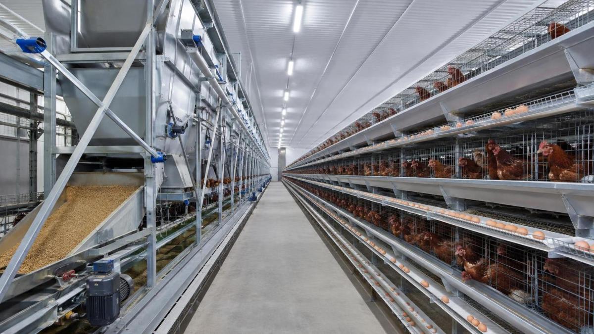
When reviewing equipment layouts or preparing a maintenance plan for a new installation, technicians may need to understand how cage structure and automation interfaces are arranged. A technical reference for a automatic layer chicken cage can help clarify the relationship between cage rows and associated feeding, egg-collection, and manure-removal equipment. Site-specific manuals, wiring diagrams, and commissioning records should remain the controlling documents for service work.
Do Not Restart Until the Cause Has Been Tested
A repair is incomplete when the equipment runs empty for a few seconds but has not been checked under conditions that resemble normal operation. After replacing a worn roller, adjusting a belt, correcting a sensor, or resetting an overload, restart in the approved sequence and observe the system through the point where the fault occurred. Watch belt tracking, transfer behavior, motor sound, sensor response, and current or overload status where monitoring is available.
If the same alarm returns, avoid repeated resets. Repeated resetting can mask a mechanical restriction, accelerate component damage, and expose personnel to an unexpected restart. Escalate the issue when there is evidence of gearbox damage, recurring electrical overheating, structural distortion, persistent tracking failure, damaged safety devices, or control faults beyond the scope of routine field service.
Downtime is limited most effectively when maintenance teams treat each fault as information. Clear isolation, systematic inspection of the material path, accurate records, and controlled restart checks turn routine service from a repair task into a practical reliability program.
Related Intelligence
- Poultry Housing & CagingCage Materials and Support Loads in Housing for 1,000 Laying HensPlanning dimension poulailler pour 1000 poules pondeuses? Discover cage materials, support loads and layout checks to help create safe, efficient housing for 1,000 laying hens.
- Poultry Housing & CagingLayer Cage Wire and Galvanizing: Durability Checks for Farms in ZambiaComparing chicken layers cages for sale in zambia? Discover essential wire, weld and galvanizing checks to choose durable cages, reduce repair costs and buy with confidence.
- Poultry Housing & CagingHow Cage Specifications Affect Poultry Housing Costs in NigeriaLocally made poultry cage price in Nigeria: compare cage specifications, housing costs, durability, ventilation, manure systems, and installation factors for smarter poultry investment.
The Morning Broadsheet
Daily chemical briefings, market shifts, and peer-reviewed summaries delivered to your terminal.