

The Authority in Global Agricultural Chemistry & Bio-Resources
Cage Materials and Support Loads in Housing for 1,000 Laying Hens
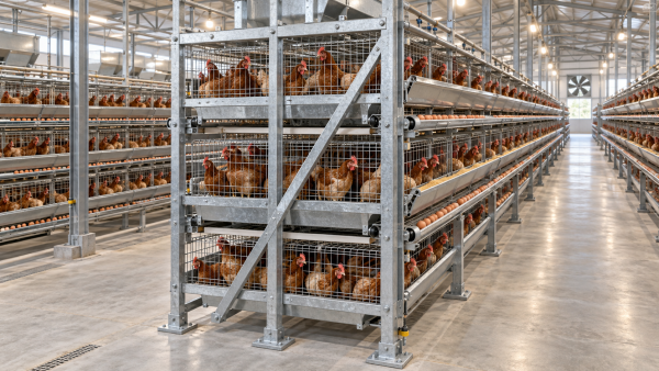
A house for 1,000 laying hens cannot be sized reliably from bird numbers alone. Cage arrangement determines the equipment footprint, but material specifications, support spacing, manure handling and service access determine whether that arrangement remains safe and usable. A compact multi-tier system may fit inside a smaller building while imposing higher reactions at its supports and making inspection more difficult.
Technical evaluation should separate three questions: how much usable accommodation the birds require, how much operating space the equipment needs, and how loads reach the building foundation. Those checks must also reflect local animal-welfare rules. Conventional cages are restricted or prohibited in some jurisdictions; where enriched cages or alternative systems are required, capacity calculations must use the applicable housing requirements rather than a supplier’s nominal bird count.
Translate flock size into a verifiable layout
Start with the permitted housing system and its usable space requirements. Dividing 1,000 by the stated birds per compartment gives a compartment count, not a building size. Capacity claims need supporting dimensions, including internal cage width and depth, tier count, usable floor area and any required enrichment provisions. External dimensions cannot substitute for usable area, especially where fittings occupy space.
The planning question expressed by dimension poulailler pour 1000 poules pondeuses brings together house dimensions, cage materials and construction. For technical assessment, these subjects belong in one coordinated drawing: cage capacity establishes the number of modules, while their frames, supports and service zones establish the building envelope. A dimensional reference is useful at this stage, but it does not replace project-specific structural or welfare verification.
Arrange the verified modules into rows before calculating the footprint. Include row-end drives, egg collection equipment, feed distribution components and manure discharge points. Some equipment extends beyond the cage body; omitting these projections can leave an apparently adequate house unable to accommodate its working machinery.
Aisle widths should reflect actual tasks. Workers need room to inspect birds, remove mortalities, repair drinkers and handle replacement components. Where carts or lifting equipment are used, check their operating envelope, not just their parked width. End clearances must accommodate maintenance and evacuation without depending on temporary removal of fixed equipment.
Height deserves a separate check. Upper tiers must remain accessible, and the gap above equipment must suit ventilation distribution, lighting and building services. Adding tiers changes more than capacity: it raises the centre of mass, increases demands on bracing and can complicate bird-level inspection.
Specify materials by component and exposure
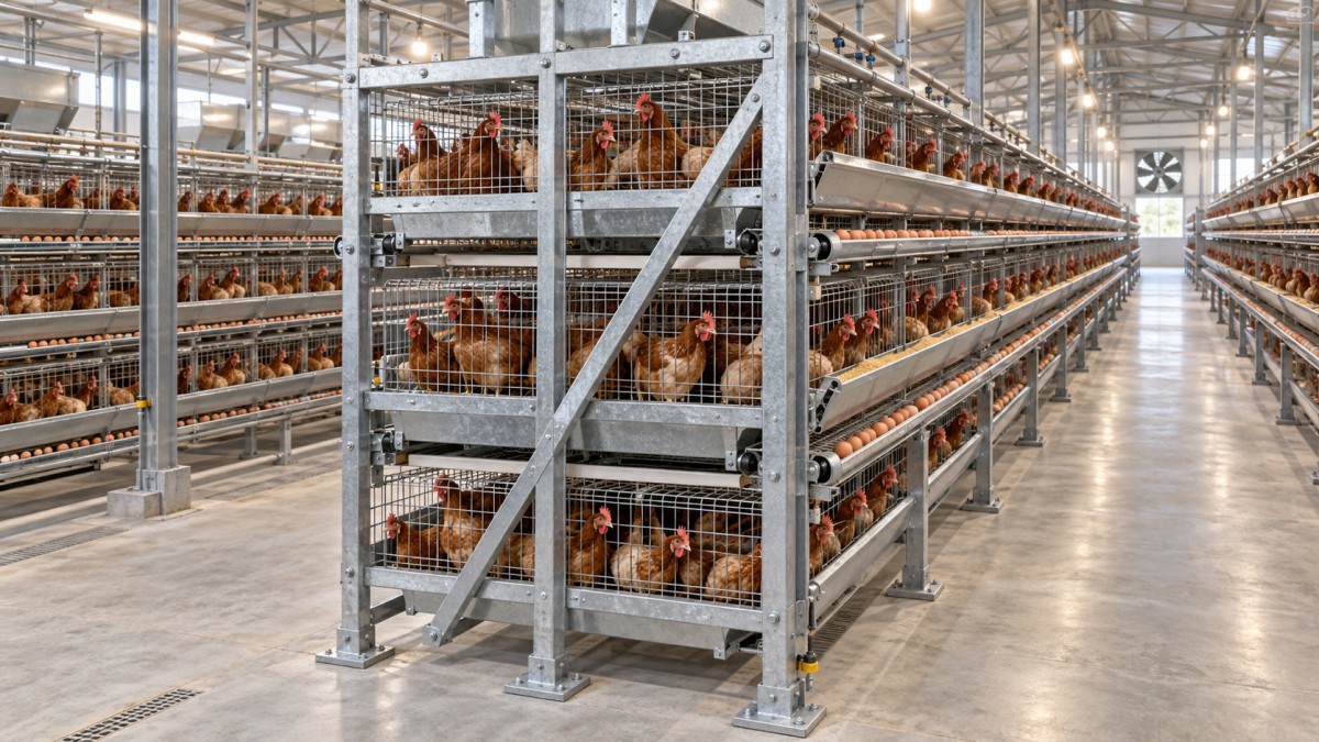
“Galvanized steel cage” is an incomplete material specification. Cage floors, partitions, main uprights, cross-members, feed troughs and fasteners perform different functions. A wire floor may be governed by stiffness, surface condition and bird contact, while an upright is governed by compression, bending and connection strength.
For wire components, request the base material, nominal diameter, permitted diameter tolerance, mesh spacing and coating specification. Small changes in wire diameter can materially affect bending stiffness. A nominal dimension without a tolerance makes it difficult to compare quotations or determine whether delivered panels match the design.
Floor geometry requires particular care. Egg roll-out depends on slope and surface condition, while bird support depends on mesh geometry and deflection. A floor that sags under occupancy can alter the roll-out path, create local low points and change how birds contact the mesh. Acceptance criteria should therefore address the loaded shape, not merely unloaded dimensions.
For structural members, identify the section dimensions, wall thickness, steel grade and manufacturing tolerances. Thin sections can appear rigid during assembly yet remain vulnerable to local buckling or connection distortion. Comparing frames by overall weight alone obscures where the material is located and whether it strengthens the load-bearing parts.
Coatings and joints need their own assessment
Poultry-house exposure can include high humidity, manure contamination, condensation and cleaning chemicals. Corrosion performance depends on coating type and thickness, coverage at welds and cut edges, and the cleaning regime. Persistent drinker leaks create local wet zones that may deteriorate faster than the rest of the cage bank.
Galvanizing wire before welding and coating an assembled component produce different coverage conditions at joints. The purchasing specification should state the intended process and how coating continuity will be checked. Neither a shiny appearance nor a general claim of “rust resistance” establishes service life.
Coated wire, stainless components and polymer parts may suit particular locations, but each introduces trade-offs. Polymer coatings require evaluation for wear, adhesion and cleaning compatibility. Stainless grades should match the exposure rather than being specified generically. Mixed-metal joints may require isolation where moisture creates a galvanic-corrosion risk.
Connections often govern reliability before the main members do. Bolts, clips, welds and brackets must transfer the intended forces without excessive slip or deformation. Check fastener grades, locking arrangements, weld quality and access for replacement. Sharp wire ends, damaged coatings and projecting fasteners also require inspection wherever birds or workers can contact them.
Build a load schedule, not a single weight estimate
The bird load is only one part of the structural assessment. A complete schedule distinguishes permanent equipment weight from variable operating loads and abnormal conditions. It should also identify which loads are carried by the cage frame and which are supported independently by the building.
- Permanent loads: cage panels, frames, troughs, pipework, fixed conveyors, drives and attached accessories.
- Operating loads: birds, feed in troughs or hoppers, water in lines, eggs awaiting collection and manure retained before removal.
- Maintenance loads: personnel and tools on designated platforms, plus forces associated with component replacement.
- Dynamic and lateral actions: equipment starting and stopping, vibration, accidental contact and any applicable seismic actions.
Use the expected maximum operating bird mass, not an assumed average without a breed or flock basis. As an illustrative calculation only, 1,000 hens at an assumed 2.0 kg each represent 2,000 kg of bird mass, equivalent to approximately 19.6 kN of gravitational load. This is not a cage design load: equipment, retained material, load combinations and design factors remain to be included.
Manure loading deserves an explicit operating assumption. Its contribution depends on removal frequency, moisture content and retention within the system. A stopped belt or interrupted removal cycle can create a load condition different from normal operation. The evaluator should define the credible accumulation condition and confirm whether it is covered by the design.
Water must be considered according to its load path. Filled drinker lines may impose a relatively modest distributed load, whereas a header tank can create a substantial concentrated load. A tank should not be assigned to the cage frame unless that frame and its connections have been designed for it.
Load combinations require engineering judgement under the applicable local design rules. Simply adding every conceivable maximum can be misleading, but checking only normal operation can miss an important failure condition. The design basis should explain which loads act together and which abnormal scenarios require separate verification.
Trace reactions from cage supports to the ground
Once loads are established, trace their path through floor panels, cross-members, uprights, base plates, anchors, slab and foundation. This exercise frequently reveals gaps between the equipment supplier’s scope and the building contractor’s scope. A frame calculation does not establish that the receiving concrete can support it.
Dividing total equipment weight by the house floor area gives an average pressure, but cages usually deliver loads through discrete feet or support lines. Those concentrated reactions can govern slab bending, local bearing and punching behaviour. Dividing the total equally among all feet is also unreliable unless the frame stiffness, support geometry and installation conditions justify that distribution.
Ask for support locations and reactions under the governing load cases, including horizontal forces and uplift where applicable. The building designer needs these values alongside base-plate dimensions and anchor details. An existing slab should be assessed for thickness, reinforcement, concrete condition, joints, cracks and the supporting ground; its suitability cannot be established from appearance alone.
Uneven installation can redistribute reactions. If one foot does not bear properly, neighbouring supports may carry additional force and the frame may twist. Levelling details, approved shims or grout, and permitted adjustment ranges should therefore appear in the installation documents. Improvised packing can create unstable contact or accelerate corrosion.
Multi-tier stability depends on bracing and restraint
Taller cage banks need a defined lateral-resistance system. Bracing, frame connections and anchors must work together rather than relying on incidental contact with walls or adjacent equipment. A brace omitted to make access easier can change the structural behaviour of an entire row.
Anchors require checks for shear, tension, concrete edge distances and interaction with slab reinforcement or joints. Where cages connect to the building frame, that frame must be checked for the transferred actions. Otherwise, equipment restraint may overload a member originally designed only for the building envelope.
Check serviceability alongside strength
A cage structure can remain below its ultimate strength limit and still perform poorly. Excessive deflection may disturb egg transfer, alter trough alignment or interfere with manure belts. Movement at joints can cause repeated adjustment, wear and noise without producing an immediate structural failure.
Set serviceability limits according to the equipment’s function. Cage-floor deformation, conveyor alignment and drive vibration require different criteria. The evaluator should request allowable tolerances from the relevant equipment designer and confirm how those tolerances will be measured after assembly and under representative loading.
Ventilation and maintenance conditions also influence material durability. Dense layouts can make leaks harder to find and wet surfaces slower to dry. Access that is adequate for routine inspection may still be insufficient for replacing a motor, belt roller or corroded upright. Those replacement tasks should be tested against the layout before approval.
Turn the assessment into procurement and acceptance checks
A technically comparable quotation needs a common design basis. Give bidders the same flock capacity, permitted housing type, building constraints, environmental exposure and manure-removal assumptions. Require departures from that basis to be stated explicitly rather than hidden in a revised layout.
The submission package should include dimensioned plans and elevations, a component material schedule, coating requirements, support reactions, connection details and installation tolerances. Structural calculations or qualified design verification should identify their scope and assumptions. General certificates cannot replace information about the equipment configuration being supplied.
Receiving inspection should check component identity, section or wire dimensions, coating damage, weld condition and fastener completeness against the approved documents. During installation, record support spacing, level, bracing positions and anchor installation. Before stocking, verify machine operation and alignment using a commissioning procedure agreed with the equipment designer; any representative loading must be controlled and safe.
The acceptance decision should rest on a coordinated package: lawful bird capacity, a workable service layout, specified materials and a verified load path into the foundation. If any one remains unresolved, a footprint that accommodates 1,000 hens is still only a space estimate—not an approved operating design.
Related Intelligence
- Poultry Housing & CagingCage Materials and Support Loads in Housing for 1,000 Laying HensPlanning dimension poulailler pour 1000 poules pondeuses? Discover cage materials, support loads and layout checks to help create safe, efficient housing for 1,000 laying hens.
- Poultry Housing & CagingLayer Cage Wire and Galvanizing: Durability Checks for Farms in ZambiaComparing chicken layers cages for sale in zambia? Discover essential wire, weld and galvanizing checks to choose durable cages, reduce repair costs and buy with confidence.
- Poultry Housing & CagingHow Cage Specifications Affect Poultry Housing Costs in NigeriaLocally made poultry cage price in Nigeria: compare cage specifications, housing costs, durability, ventilation, manure systems, and installation factors for smarter poultry investment.
The Morning Broadsheet
Daily chemical briefings, market shifts, and peer-reviewed summaries delivered to your terminal.