

The Authority in Global Agricultural Chemistry & Bio-Resources
How Cage Tiers and Aisle Width Affect a 1,000-Layer House Layout
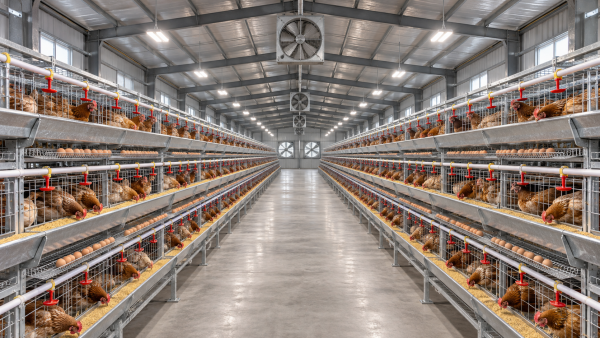
A 1,000-layer house cannot be sized reliably by dividing the flock by a nominal number of birds per cage and drawing rows around the result. Adding cage tiers can shorten the rows or reduce their number, but it also changes working height, manure handling and ventilation. Wider aisles make inspection and equipment movement easier, yet can increase the building footprint enough to offset some of the space saved by stacking.
The practical design question is how to fit usable cage capacity, workable circulation space and environmental equipment into the same building. A plan that accommodates the birds on paper may still be difficult to clean, inaccessible for maintenance or unsuitable for the applicable welfare rules. The dimensions below are illustrative calculations, not equipment specifications or recommended stocking densities.
Start with usable capacity, not building dimensions
Define the design flock as the maximum number of laying hens expected to occupy the house at one time. Then establish the permitted and practical capacity of the proposed cage system. The calculation depends on usable floor area, cage configuration, feeder and drinker access, and the rules applicable to the location and production system. A manufacturer’s nominal capacity should not be treated as proof that a particular stocking arrangement is compliant.
For a preliminary layout, identify the number of birds allowed per cage module and the number of modules along each row and tier. The basic check is:
Total places = places per module × modules per tier per row × tiers × rows.
Suppose a hypothetical compliant assessment permits five birds per module. With four rows, three tiers and 17 modules per tier per row, the arithmetic gives 1,020 places. The extra 20 places are a consequence of whole modules; they are not a recommendation to exceed a flock limit or to stock every module at its maximum. The assumed five-bird figure is solely for illustrating the layout calculation and must be verified for the actual equipment.
Module count is only the beginning. A drawing must also include the physical pitch of each module, structural end frames, drive units, feed distribution equipment and space to reach components. Egg belts or collection tables can project beyond the cage body. If those projections are omitted, a calculated row length may not fit between the building walls.
How adding tiers changes the footprint
Keeping the illustrative five-place module and four-row arrangement, three tiers require 17 whole modules along each tier to reach at least 1,000 places. Four tiers require 13 modules: 5 × 13 × 4 × 4 = 1,040 places. The higher arrangement uses fewer modules along each row, although its total cage count is slightly greater because capacity comes in whole-module increments.
If the hypothetical module pitch along the row is 0.60 m, the cage modules alone occupy 10.2 m in the three-tier example and 7.8 m in the four-tier example. These are not full house lengths. Both require allowances for end frames, access and equipment, and the shorter cage row does not automatically produce an equally shorter building. The calculation simply isolates the effect of tiers when other assumptions are held constant.
More tiers can also affect the building section. The roof and structural design must accommodate the top tier, service clearances, lighting and air distribution. Operators must be able to inspect birds and reach drinkers, feeders and doors at the upper level without creating an unsafe routine. Where a platform or access device is needed, its storage and movement space belong in the plan, not just in the operating manual.
The loads carried by floors and supports also change with the selected equipment and its operating condition. The structural designer needs the supplier’s load information, including cage assemblies, birds, feed, manure and any maintenance loads the structure must support. A smaller footprint should not be accepted as a saving until the implications for structure and access have been priced.
Aisle width is a layout input, not leftover space
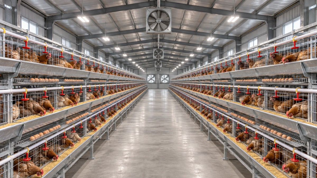
Draw the aisles around the actual tasks: observing birds, removing equipment, collecting or handling eggs where relevant, moving tools, cleaning and responding to an emergency. An aisle that permits a person to walk through may still be too narrow to open cage doors fully or pass a trolley while another worker is present.
Measure clear width between the furthest permanent projections, rather than between cage frames. Feed troughs, pipes, egg conveyors, column bases and protective guards can all reduce usable clearance. A door that opens into an aisle creates a temporary obstruction; its full opening arc should be checked against the opposite row and any required escape route.
The effect on building width is straightforward. For a hypothetical cross-section containing four cage rows and three internal aisles, increasing each aisle by 0.20 m adds 0.60 m to the internal width, provided row widths and wall-side spaces stay unchanged. For a 20 m internal building length, that represents 12 m² of additional floor area. The 20 m length is an illustration, not a recommended house size. Wall thickness, foundations and exterior dimensions remain separate considerations.
Do not assume that all aisles must be identical. A route used for equipment removal may need a different clearance from a routine inspection passage, subject to local requirements and the equipment layout. Differences should be shown explicitly on the drawing so installers do not position rows using a single nominal spacing.
Turn cage dimensions into a house-size estimate in meters
A useful preliminary width calculation is the sum of the installed row widths, clear aisles, wall-side clearances and any internal obstructions. For length, add the installed row length, equipment projections and clear working spaces at both ends. Use internal dimensions for this exercise, then add the wall construction to obtain external building dimensions.
Consider an illustrative plan with four installed rows, each 1.20 m wide; three internal aisles of 1.00 m; and two wall-side clearances of 0.80 m. Its internal width is 9.40 m. If the installed cage and equipment length is 12.00 m, with 1.50 m clear at each end, the internal length is 15.00 m. The resulting rectangular area is 141 m².
Those inputs are assumptions for arithmetic, not a design recommendation. The width assumes each row dimension includes all fixed projections and that the specified clearances remain unobstructed. The length assumes both end spaces are adequate for the actual doors, drives and work tasks. The example also excludes separate rooms or areas for feed storage, egg handling, utilities and manure equipment. A different arrangement can require more or less space even for the same flock.
During equipment comparison, the dimensions associated with a typical 1,000-layer cage arrangement provide a useful reference alongside the view poultry equipment details material. Any published dimensions still need to be reconciled with a supplier’s installation drawing, local conditions and the evaluator’s own capacity calculation.
Ventilation, manure and tier access affect one another
Stacking birds changes where heat, moisture and air contaminants are generated within the house. Ventilation design must account for the occupied volume and airflow at different tier heights, not just the building’s floor area. Equipment layout can obstruct airflow or create uneven conditions if inlets, fans and cage rows are considered separately.
Request a ventilation proposal for the design flock and local climate, including how the system operates across expected weather conditions and how air reaches the upper and lower tiers. The ventilation designer should also identify what happens during equipment failure and how alarms or backup provisions are addressed under applicable requirements. Building height alone does not establish that air quality or temperature will be acceptable.
Manure removal affects both the cross-section and the end of the house. A system using belts, scrapers or another collection arrangement may need drives, discharge equipment and access for cleaning. Confirm whether manure travels to an external collection point and whether the route conflicts with doors, egg handling or vehicle access. The amount of space required depends on the selected system; it should be established from drawings rather than assumed from the cage footprint.
Water lines and feeding equipment deserve the same coordination. Check how lines are isolated, cleaned and reached on each tier, and whether a repair requires removing cages or entering a narrow gap. An upper tier that fits below the roof may still be impractical if a worker cannot see drinker lines or replace a component safely.
Compare layouts on a common basis
When evaluating bids, ask each supplier to use the same flock size, site constraints and required functional spaces. Comparing a compact cage footprint from one proposal with another supplier’s complete building plan will distort the decision. Keep the following items visible in the comparison:
- Capacity basis: module dimensions, usable area, birds per module and the welfare or legal basis used to determine capacity.
- Installed envelope: row pitch, total row length, tier height, fixed projections and equipment at each end.
- Circulation: clear aisle widths, wall-side access, door swings and the route for removing the largest serviceable component.
- Utilities and environment: ventilation assumptions, water and power connection points, manure discharge and provisions for equipment failure.
- Scope and interfaces: which party supplies supports, building openings, electrical work, installation and commissioning.
Costs should follow the same boundaries. More tiers may reduce the length of cage rows while increasing the cost or complexity of access equipment, structural work or services. Wider aisles can increase floor and building-envelope area, but a narrow layout may impose recurring labor costs if routine tasks require awkward handling or equipment disassembly. Neither outcome can be established from cage price alone.
Verify the drawing before the building is fixed
A coordinated plan should show dimensions in meters, equipment heights and sections through the rows. Mark both nominal equipment dimensions and minimum clearances after installation. Review the route from delivery entrance to final position: a cage component that fits inside the completed house may not pass through the specified opening or turn into its aisle.
Before acceptance, compare the installed system with the approved drawing. Check row spacing at several points, door operation, access to drives and isolation devices, and the clearance needed to remove wear parts. Confirm that any as-installed changes are reflected in the operating and maintenance information. A small shift in a row may be inconsequential in an open area but significant beside a column, doorway or conveyor drive.
For welfare and regulatory checks, use the requirements that apply to the site and production system rather than treating the illustrative dimensions as standards. Relevant reference materials include the World Organisation for Animal Health, Terrestrial Animal Health Code, Chapter 7.11, “Animal Welfare and Laying Hen Production Systems,” and, where applicable, European Union Council Directive 1999/74/EC, which sets minimum standards for the protection of laying hens. Local rules and certification schemes may impose additional or different conditions.
The defensible choice is the layout that accommodates the verified flock capacity and all required work within the actual building constraints. Tier count and aisle width should be settled together, then checked against equipment drawings, operating tasks and the applicable requirements before the building dimensions become fixed.
Related Intelligence
- Poultry Housing & CagingHow Cage Tiers and Aisle Width Affect a 1,000-Layer House LayoutView poultry equipment details and discover how cage tiers and aisle widths shape a practical, efficient layout for a 1,000-layer house.
- Poultry Housing & CagingHow to size chicken layer cages for the intended stocking densityGet chicken layer cage dimensions right: learn to calculate usable floor area, check feeder and drinker access, and avoid costly stocking errors before you buy.
- Poultry Housing & CagingBattery Cage Buying Basics: Matching A-Type Systems to Farm LayoutBattery cage buying starts with the right layout. Discover how to match A-type systems to your poultry house, check compliance, and avoid costly installation mistakes.
The Morning Broadsheet
Daily chemical briefings, market shifts, and peer-reviewed summaries delivered to your terminal.