

The Authority in Global Agricultural Chemistry & Bio-Resources
How Modular Feed and Grain Systems Support Scalable Storage and Processing Expansion
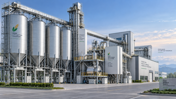
Capacity expansion in feed and grain facilities often fails at the interfaces: a new storage bin is installed before downstream conveying is ready, a mill receives more raw material than its batching line can absorb, or a loading lane becomes the limiting point after upstream equipment has been upgraded. Modular feed and grain systems address this problem by treating storage, transfer, conditioning, grinding, mixing, pelleting, and loadout as expandable blocks with defined mechanical and control connections.
The practical value is not simply faster construction. A modular arrangement creates a sequence for adding capacity without committing the entire site to its final footprint on day one. The first phase can establish receiving, base storage, and a transfer spine; later phases can add bins, process modules, duplicate critical transfer routes, or separate finished-product handling. Expansion then follows actual throughput constraints rather than an early forecast that may change before the facility reaches full utilization.
Start with the material path, not the equipment list
A scalable layout begins by mapping how material moves through the plant under normal, peak, and abnormal conditions. Grain entering by truck, rail, or barge has a different arrival profile from ingredients delivered in bags, bulk tankers, or intermediate containers. The system must show where each material is received, sampled, cleaned, stored, reclaimed, weighed, processed, and dispatched. A block layout that only shows nominal flow can conceal the conditions that govern expansion: simultaneous receiving and shipping, ingredient substitutions, wet material segregation, rework return, and cleaning access.
For example, adding storage capacity does not automatically increase usable intake capacity. If an existing pit, elevator boot, dust collection point, or truck circulation lane remains undersized, larger bins may merely lengthen the time material waits outside the facility. Likewise, a new hammer mill or pellet line may not deliver its rated output when the upstream dosing system cannot replenish bins at the required rate or when finished-feed loadout repeatedly interrupts process flow.
A useful early exercise is to trace each material through the facility and identify its limiting interface:
- Receiving interface: unloading rate, pit volume, foreign-material removal, sampling, and the route from intake to the intended storage destination.
- Storage interface: bin geometry, live capacity rather than nameplate volume, reclaim behavior, aeration or conditioning needs, and the ability to isolate one commodity from another.
- Process interface: surge capacity before grinding, dosing accuracy at batch scales, residence time in conditioning equipment, and whether the next module accepts continuous or batch flow.
- Dispatch interface: finished-product bins, route selection, scale access, loading rate, and the ability to keep shipment activity from backing into production.
These interfaces should be evaluated at the same time as the proposed module. A modular conveyor gallery, for instance, is only expandable when its supporting structure, transfer towers, electrical distribution, access clearances, and discharge positions were arranged for future branches. Adding a flange or spare outlet alone does not guarantee that a later conveyor can be installed without dismantling surrounding equipment.
Define expansion blocks around independent functions
Modules work best when each one performs a recognizable operational function and has clear boundary conditions. A raw-grain storage block may include receiving discharge, bucket elevator discharge points, bin venting, level measurement, reclaim gates, and a common takeaway conveyor. A process block may contain a pre-grind bin, feeder, mill, aspiration, magnet, and discharge conveyor. Treating these components as a unit prevents a frequent design error: purchasing the main machine while leaving support equipment, controls, and maintenance access to be resolved during installation.
Functional boundaries should also reflect how the plant will operate during later construction. A new module should be capable of being commissioned without leaving the existing route unusable for an extended period. This usually requires isolation gates, temporary bypass routes, defined lockout points, and controls that can distinguish an active production route from a construction zone. Where an old and new conveyor merge, the control logic needs positive route selection and interlocks that prevent material from feeding into a stopped downstream machine.
Standardized module dimensions reduce uncertainty, but standardization should not be confused with identical equipment everywhere. The frame size, bolt pattern, cable tray path, access platform elevation, and controller interface can be repeatable while the actual feeder, bin, or conveyor is selected for the material and duty. A high-fat meal, a fine mineral premix, and free-flowing whole grain do not behave alike at hoppers or transfer points. Using the same hopper angle or feeder type across all materials can create bridging, segregation, carryover, or unstable dosing even though the physical modules appear consistent.
Storage capacity must be separated from flow capacity
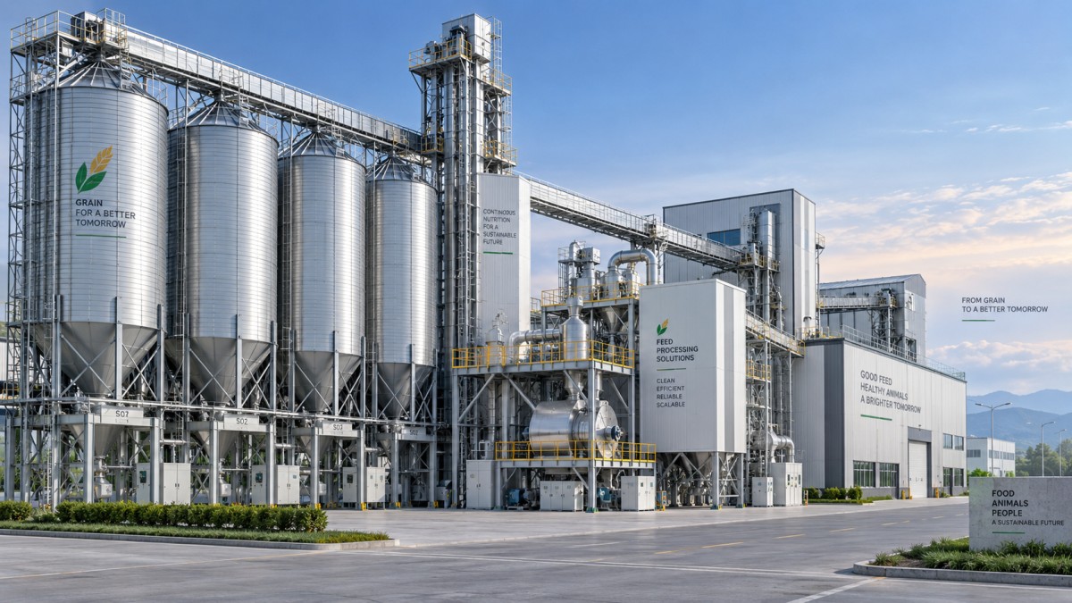
Storage is often described in tonnes or bushels, yet the usable value of a storage block depends on how material enters and leaves it. A bin may have enough gross volume for a planned inventory position but insufficient outlets to feed several downstream routes. Conversely, a large central bin can create operational rigidity when different grades, moisture conditions, or ingredient lots need segregation. Modular storage favors smaller expandable banks when material variability, traceability, or recipe changeovers matter more than holding a single large volume.
Bin selection requires attention to the material's bulk density, angle of repose, moisture condition, particle size distribution, and tendency to compact during storage. These characteristics affect the true inventory, wall friction, hopper discharge behavior, and the force imposed on extraction equipment. Nameplate volume calculated for one commodity should not be treated as a universal capacity figure. The same physical bin will hold materially different masses of wheat, maize, soybean meal, mineral blends, or finished pellets.
The planned reclaim mode also changes the right design. First-in, first-out flow may be necessary where material condition or lot rotation must be controlled. Mass-flow hoppers promote more uniform discharge but demand suitable geometry, surface finish, and outlet design. Funnel-flow arrangements can be adequate for stable, free-flowing materials, but stagnant zones create problems when ingredients are prone to bridging or when carryover between formulations is unacceptable. A modular expansion plan should preserve the option to add reclaim points rather than assume one existing outlet will serve every future route.
Expand conveying routes without creating hidden choke points
Conveying is where phased projects frequently lose their flexibility. A new storage row can be structurally simple, but the route that fills it and the route that reclaims from it may cross existing traffic, compete for a single elevator, or require a transfer tower with no spare discharge position. The future path should be represented in the initial general arrangement, even when its conveyor is not installed. That includes required elevation, turning radius for enclosed conveyors, headroom beneath galleries, support foundations, and safe access for servicing drives and bearings.
Conveyor selection follows material behavior and route geometry. Drag conveyors offer enclosed horizontal movement and multiple discharge options, but wear can increase with abrasive material and chain tension must remain accessible for adjustment. Belt conveyors suit longer, gentler routes and can offer lower product damage for some materials, yet transfer points require careful containment. Screw conveyors fit short, controlled transfers but can degrade pellets, compact some products, or produce uneven discharge over longer runs. Bucket elevators provide vertical lift in a small footprint, although their boot design, cleanout access, and explosion protection strategy require coordination with the wider plant design.
Rated conveyor capacity should not be read in isolation. A conveyor rated above the process requirement may still cause trouble if the receiving hopper has too little surge volume, if the downstream feeder requires a steadier flow, or if the speed range cannot accommodate low-rate recipes. At the other extreme, running a transfer route continuously near its practical limit leaves little recovery capacity after a truck unloading delay, a process stoppage, or a batch change. The design target is a stable operating window, not merely the highest calculated tonnes per hour.
Build controls as an expandable operating architecture
Physical modularity is weakened when every expansion requires a full rewrite of the control system. Each module should have a defined set of signals: run permissives, fault status, speed reference where relevant, level alarms, local isolation state, and upstream/downstream handshake signals. A consistent tag structure and control narrative allow later equipment to be integrated without making existing routes difficult to diagnose.
Control cabinets and network infrastructure need reserved capacity, but spare hardware alone is not enough. The program should distinguish between equipment that is absent, installed but isolated, available for automatic routing, and under maintenance. This distinction matters during phased commissioning. A route-selection screen that treats a future branch as a failed branch can generate nuisance alarms or block an otherwise valid material path. Conversely, a branch accidentally enabled before commissioning can send product into an unprepared bin or conveyor.
Instrumentation should be selected for its operating purpose rather than added uniformly. High-level detection protects against overfill; it does not replace inventory measurement where formulation planning depends on material quantity. Load cells can support inventory control and dosing verification, but structural restraint, thermal movement, and flexible connections influence their reliability. Bin level devices may respond differently to dusty grain, lightweight meal, or materials that form uneven surfaces. The installation location, probe type, and alarm logic must be evaluated together.
Sequence construction around operating continuity
A phased expansion needs a construction sequence that recognizes the facility's production calendar and material commitments. Work that interrupts a common elevator, transfer conveyor, or finished-feed route should be grouped into planned outages, while independent foundations, steelwork, remote bins, and cable containment can proceed with less impact. The schedule should identify each tie-in point, its isolation method, the duration of restricted access, and the condition required before the existing route returns to service.
Site verification before fabrication is especially important when connecting modular equipment to an operating plant. Field dimensions, actual equipment elevations, building columns, underground utilities, and existing cable routes often differ from legacy drawings. A small elevation mismatch at a conveyor discharge can lead to an unsuitable chute angle, inadequate clearance for a maintenance cover, or a transfer point that retains material. Laser surveys and physical checks at the proposed interfaces reduce the chance that a nominally modular package becomes a field-modification exercise.
Material delivery and lifting plans deserve equal attention. Long conveyor sections, preassembled galleries, bins, and dust-collection ductwork may be efficient to fabricate off-site but difficult to position once surrounding plant areas remain active. Module dimensions must be checked against gate widths, internal travel paths, crane reach, overhead obstructions, and the order in which components can enter the site. Splitting equipment into transport sections changes the installation labor, alignment requirements, and number of potential leakage or dust escape points.
Commission each phase against defined operating conditions
Mechanical completion is not the same as production readiness. Before material is introduced, each route should be verified for rotation direction, guarding, cleanout closure, emergency stops, interlocks, access platforms, and dust collection connections. Dry commissioning confirms that motors, sensors, gates, and sequences react correctly. Material commissioning then reveals issues that no empty test can show: dust accumulation at transfer points, poor hopper drawdown, carryback on belts, unstable feeder output, pellet breakage, or material remaining in inaccessible sections.
Acceptance criteria should reflect the function of the installed phase. A new storage module needs proof that it fills, vents, measures level, isolates, and reclaims along the intended route. A processing module needs confirmation that its feed rate is controllable, its safety interlocks behave correctly, and its discharge does not overload the next operation. Recording these conditions creates a reliable baseline before the next expansion changes the system again.
Modularity supports scalable growth when future connections are deliberately protected, material behavior is treated as a design input, and each added block is commissioned as part of a working flow path. The strongest expansion plans leave room for change without leaving critical interfaces undefined.
Related Intelligence
- Grain Silos & StorageHow Modular Feed and Grain Systems Support Scalable Storage and Processing ExpansionModular feed and grain systems enable smarter, scalable expansion across storage, conveying, processing, and loadout. Discover how to eliminate bottlenecks, protect future capacity, and keep operations moving.
- Grain Silos & StorageHow to Size a Grain Pre-Cleaner for Capacity, Crop Type, and Impurity LoadGrain pre cleaner machine sizing guide: match capacity, crop type, moisture, and impurity load to improve flow, separation quality, and downstream performance.
- Grain Silos & StorageHow Can You Verify That a Grain Handling System Meets Export Standards?How do I know if a grain handling system meets export standards? Explore practical checks for traceability, sanitation, quality control, and export-ready compliance.
The Morning Broadsheet
Daily chemical briefings, market shifts, and peer-reviewed summaries delivered to your terminal.